
This is an archive of Physics 4B conceptual questions. The last semester these questions (and answers) were used was in Fall 2024 class, and with the recent re-organization of the course material, I don’t anticipate using them again, so this is a kind of “resting place” for this material.
General Instructions
[ARCHIVAL NOTE: Below are the general instructions used at the beginning of the conceptual questions set, under the “Instructions” heading]
This is a peer-graded assignment. After the assignment due date, you will be assigned 3 peer reviews for this assignment. Please follow the instructions in the peer review assignment (which also contains model answers and grading notes) to complete the peer reviews.
The conceptual questions below, some from the textbook and others that relate to the topics covered in the textbook, can mostly be answered adequately in one paragraph or so. If you see more than three questions, you only need to answer up to three questions for a complete submission.
Please answer the following three (3) conceptual questions in your response to this assignment. Use of text box for online submission is highly recommended.
[ARCHIVAL NOTE: Below are the general instructions used at the end of the conceptual questions set, immediately after the last question]
Please click on “Submit” button at the top of this page to submit your answers. Use of text box for online submission is highly recommended (text box has advanced editing options that can meet most needs). Use the file upload option if you have to upload images or PDF for your answers.
[ARCHIVAL NOTE: Below are the general instructions—under the “Instructions” heading—used at the beginning of the “peer review” assignment, which contained the model answers]
After the due date for [LINK to CONCEPTUAL QUESTIONS SET], you should have been assigned up to three classmates’ submissions for peer review. The links to these assignments are available within the page for [LINK to CONCEPTUAL QUESTIONS SET]; look for the links near the portion of the page showing your own submission info, either on the right side of the page or the bottom, depending on the size of your web browser window.
Please review the submissions using the provided rubric; mark the rubric based on the completeness and evidence of effort demonstrated. For a peer review to be considered complete, you must fill out the grading rubric, separately for each submission. I do encourage you to observe how your peers’ submissions compare to your own and leave an encouraging feedback. You can leave comments either within the rubric or outside of the rubric. Do please note that your peers cannot respond to you, as peer review communications only go one way, from the reviewer to the reviewee.
In case it’s helpful, below section provides model answers to the associated conceptual questions.
[ARCHIVAL NOTE: Below are the general instructions—as additional sections—used at the end of the “peer review” assignment]
Late Peer Reviews – There is some limited grace period between the peer review due date and when I assign peer review scores. Beyond this, please note there will be no extensions. Peer reviews must be received on time for them to be useful to the people you are reviewing. If you do not see any peer reviews assigned to you and it’s past peer review deadline, it’s because I removed all incomplete peer review assignments when I gave peer review credit.
“Mark as Done” – You must mark this assignment as done before you can move onto the next item in the Module. In this class, “mark as done” simply means you take responsibility for knowing the information on the page (whereas “view” requirement simply means your web browser accessed the information). So, if you feel you understood what is on this page and you take responsibility, please mark it as done, so that you can move on to the next page.
Rubrics
[ARCHIVAL NOTE: Below are “Conceptual Questions Rubric“, same rubric repeated for Questions 1, 2, and 3]
Conceptual Question 1: Completeness of the response to Conceptual Question 1 (or one of three questions answered)
- 2 pts – Complete: The response is clearly marked as a response to Conceptual Question 1 (or one of three questions answered) and demonstrates a good-faith effort at answering the question.
- 1 pts – Incomplete: The response is not clearly marked as responding to Conceptual Question 1 (or one of three questions answered) and/or good-faith effort at answering the question is not evident.
- 0 pts – No response: No response can be matched up to Conceptual Question 1 (or one of three questions answered).
[ARCHIVAL NOTE: Below is “Peer Review Rubric”]
Completeness: Completeness of peer reviews with evidence of effort.
- 3 pts – Complete: All three assigned peer reviews have been completed with a clear evidence of effort shown.
- 2 pts – Incomplete: One or more of peer reviews have not been completed, and/or lack of good-faith effort in the completed peer review(s) is evident.
- 0 pts – No reviews: None of the three assigned peer reviews have been completed in a meaningful way.
Thermal Physics Intro (questions and model answers)
Q1 – [OpenStax, Chapter 1, Question 4] Give an example of a physical property that varies with temperature and describe how it is (or can be) used to measure temperature.
A1 – “Examples of physical properties that can be used to measure temperature”: Following are the examples that can be found in the textbook itself: (a) thermal expansion (used in mercury/alcohol thermometer, and other thermometers using bimetallic strips), (b) electrical resistance (resistance of a thermometer has a dependence on temperature), (c) color (some materials change color at specific temperatures, see Figure 1.3), (d) emission of infrared radiation (peak wavelength depends on temperature). There are additional physical properties that are not listed in the textbook (that you might have found on research). Thermocouple effect is the biggest one (many temperature probes work on this effect). Melting points and boiling points of known substances can be used to calibrate thermometers. The ideal gas law (covered in Chapter 2) also points at a way temperature can be inferred from knowing other properties of a sample of gas.
Q2 – “Invar“, a nickel-iron alloy mentioned in the textbook, is a special metal alloy with a distinguishing feature from all other metals and alloys. What is this distinguishing feature and how does it work?
A2 – “What is invar”: The distinguishing feature of invar is its very low coefficient of thermal expansion. At about  , the coefficient of linear expansion of invar is about 10 times lower than iron (whose
  coefficient of linear expansion is already the lowest among base metals). This is why it is named “invar” (from “invariant”), and it is used in applications where exact physical dimensions and tight tolerances are important. The second part of the question is a bit of a trick question, since, as the Wikipedia page states, “A detailed explanation of Invar’s anomalously low CTE has proven elusive for physicists.” That is, no one is sure how it works; people have measured expansion coefficients for different alloy ratios, and the one used for invar happens to be at the minimum. (It is not necessary to explain everything for something to be useful.)
Q3 – [OpenStax, Chapter 1, Question 15] A pressure cooker contains water and steam in equilibrium at a pressure greater than atmospheric pressure. How does this greater pressure increase cooking speed?
A3 – “How does pressure cooker cook faster”: It’s not the higher pressure that increases the cooking speed, it is the higher temperature reached inside the pressure cooker. Because boiling is a cooling process, the maximum temperature achievable in a water boiling at 1 atmosphere of pressure is 100°C. By allowing pressure to build up and not allowing water to boil (a liquid only boils when its saturated vapor pressure is equal to the ambient pressure), the water inside a pressure cooker can be heated to a temperature greater than 100°C, and this higher temperature cooks food faster.
Q4 – [OpenStax, Chapter 1, Question 20] How does the latent heat of fusion of water help slow the decrease of air temperatures, perhaps preventing temperatures from falling significantly below 0°C, in the vicinity of large bodies of water?
A4 – “Why are winter temperature near large body of water not much below 0°C”: Freezing is a warming process. When liquid water freezes into ice, it transfers heat from itself to the surrounding (“latent heat of fusion”; melting is the reverse process). This heat released to the surrounding helps keep the surrounding (air, land, etc.) warm around 0°C, temperature where water freezes and latent heat of fusion is released. Large bodies of water are responsible for other microclimate effects, primarily through its large specific heat capacity (the body of water can absorb or release large amounts of heat with relatively small changes in temperatures).
Q5 – [OpenStax, Chapter 1, Question 30] Shown on the right is a cut-away drawing of a thermos bottle (also known as a Dewar flask), which is a device designed specifically to slow down all forms of heat transfer. Explain the functions of the various parts, such as the vacuum, the silvering of the walls, the thin-walled long glass neck, the rubber support, the air layer, and the stopper.
A5 – “Explain the functions of the various parts of thermos”: Different parts of thermos work together to limit transfer of heat from the innermost layer to the surrounding. In the order listed in the question: (a) the vacuum limits heat transfer by preventing heat transfer by convection or conduction between the two layers of glass walls, (b) the silvering of the glass walls further limit heat transfer by minimizing heat transfer by radiation (black surfaces absorb/emit radiation better; shiny surfaces absorb/emit radiation least well), (c) the thin-walled long glass neck limits heat transfer by conduction between the inner layer of glass wall and outer layer of glass wall (the shortest path has already been stopped by the vacuum layer), (d) the rubber support limits conduction between the outer glass wall and the outer-most layer of thermos (rubber is a good insulator) while providing structural support, (e) the air layer also limits conduction, since air is also a good insulator (and a thin layer of air also transfers heat poorly, due to smaller convection cells), and (f) the stopper at the top limits heat transfer by convection out of the thermos (particularly necessary if the thermos contains hot liquid; not as necessary if thermos contains cold liquid). All parts of thermos are designed to stop or slow one or more of the three heat transfer mechanisms, conduction, convection, and radiation.
Q6 – [OpenStax, Chapter 2, Question 12] Experimentally, it appears that many polyatomic molecules’ vibrational degrees of freedom can contribute to some extent to their energy at room temperature. Would you expect that fact to increase or decrease their specific heat capacity per molecule from  ?
?
A6 – “How does vibrational degree of freedom affect heat capacity”: The question is referring to what is evidenced in Figure 2.13 (see on right). For a diatomic molecule, it may have up to 7 degrees of freedom (3 translational degrees of freedom, 2 rotational degrees of freedom, and 2 vibrational degrees of freedom). However, instead of having a heat capacity per molecule of
 , at room temperature, most diatomic molecules only have heat capacity per mole of
  , corresponding to 5 total degrees of freedom. (This is referred to as “freezing out” of vibrational degrees of freedom.) If vibrational degrees of freedom are not completely “frozen out”, then this will increase the specific heat capacity of the gas, because, for a given change of temperature, there are “more places” where heat can be transferred to (5 degrees of freedom, for translational and rotational motion, and some fraction of degrees of freedom corresponding to vibrational motion). This is also shown in Figure 2.13, where at higher temperatures, the specific heat capacity per molecule increases to
First Law (questions and model answers)
Q1 – [Based on OpenStax, Chapter 3, Question 2] A change in internal energy can be caused by heat transferred, by work done, or by a combination of the two. Describe and explain how you would distinguish between three cases. [Hint: What measurable macroscopic physical variable changes with a change in internal energy? With work done?]
A1 – “Relating change in internal energy to heat transfer and work”: Aside from being told directly how the change in internal energy occurred (for example, description of a process as “adiabatic” tells you directly that no heat transfer took place), of the three quantities, internal energy change, heat transfer, and work done, it is almost always easier to find out work done and internal energy change directly. Because doing work necessarily involves change of volume, from measurements of pressure and volume, you can calculate work done directly. Internal energy change can also be directly calculated from temperature change (and temperature change can be calculated from pressure and volume, using the ideal gas law). Measuring heat transfer directly is more difficult; in most cases, heat is calculated from internal energy change and work done by use of First Law ( ).
).
Q2 – [OpenStax, Chapter 3, Question 5] Is it possible for the temperature of a system to remain constant when heat flows into or out of it? If so, give examples.
A2 – “Constant temperature with heat transfer”: Yes. In isothermal expansion or contraction, the process occurs without a change of temperature. In addition, because expansion and contraction involves work done (according to  ), in order for the First Law to be obeyed (
 , and
, and  for isothermal process, since temperature change is zero), there must be heat flow into or out of the system, to provide the energy for the work done.
Q3 – [OpenStax, Chapter 3, Question 8] A great deal of effort, time, and money has been spent in the quest for a so-called perpetual-motion machine, which is defined as a hypothetical machine that operates or produces useful work indefinitely and/or a hypothetical machine that produces more work or energy than it consumes. Explain, in terms of the first law of thermodynamics, why or why not such a machine is likely to be constructed. [Note: We will defer the piece relating to the second law of thermodynamics until later.]
A3 – “Impossibility of perpetual motion machine, First Law version”: Because energy is conserved, it is impossible for a machine that produces more work than the energy it uses up to exist (that would allow net energy to be created). In more specific terms of First Law, the energy for work done must come from some source of energy, either heat transfer or reduction in internal energy. This is often humorously summarized as “You can’t win.” First Law does leave open a possibility of machine that moves indefinitely, provided that it does no net work (no energy is taken out of it). We will come back to this with the Second Law.
Q4 – In describing thermodynamic processes, four processes are given special names based on a restriction they follow. Name these four processes and describe the restrictions they follow. And answer this question: do all thermodynamic processes fit into one of these four processes?
A4 – “Four special named thermodynamic processes“: The four special named thermodynamic processes are: isothermal, isobaric, isochoric, and adiabatic:
- Isothermal: It means temperature is constant (please don’t confuse this with adiabatic; there is heat transfer in an isothermal process).
- Isobaric: It means the pressure (“-baric”) is constant.
- Isochoric: It means the volume (“-choric”, from Greek meaning “space”) is constant. It also goes by the name “isovolumetric”, which I will never use again, as it is an ugly term that mixes a Greek prefix (“iso-“) with a Latin root (“volume”).
- Adiabatic: It means no heat transfer (so any work done results in temperature change). Please note that the word “adiabatic” is used elsewhere in physics (e.g. adiabatic approximation in quantum mechanics), and in different contexts, its meaning is slightly different (although there is a common theme).
There are many thermodynamic processes that do not fit into one of these four. On a P-V diagram, each of these four processes are illustrated with curves of particular shape (isobaric is horizontal; isochoric is vertical; isothermal looks like 1/x; adiabatic looks similar to isothermal but is steeper). Any thermodynamic process that can be diagrammed on P-V diagram and does not fit one of these shapes does not also fit into one of the four restrictions above.
Q5 – When describing heat capacity of a gas, the condition under which the gas is heated is always specified, because heat capacity of a gas under constant volume ( ) and heat capacity of a gas under constant pressure (
 ) are different. Specifically, heat capacity of a gas under constant pressure is greater than heat capacity of a gas under constant volume (
 ). Explain, conceptually, why this is. (If necessary, use equations, but given the same correctness, conceptual explanation is superior.)
A5 – “Why is CP greater than CV“: To put simply, “because a gas being heated under constant pressure must do work.” This one sentence (well, sentence-fragment) answer is correct and sufficient for this question, but I will explain further now for the sake of completeness: For a constant-volume process (which CV is associated with), we are guaranteed that no work is done, so any heat transferred goes into changing the temperature (which is directly proportional to internal energy). However, for a constant-pressure process, if you heat it up (transferring heat, trying to increase its temperature), according to the ideal gas law, its volume must be increasing also, and this change of volume under pressure means it is doing work ( ). So, according to the First Law, some of the heat input must go into doing work (
 ), meaning less energy from heat transfer is available for increasing temperature of the gas. Since, for the same heat transfer, the amount of temperature change is less for constant-pressure process, the specific heat capacity for constant-pressure is greater (more heat transferred for same temperature change) than for constant-volume. And a similar argument holds when you are removing heat, cooling the gas either under constant-volume or constant-pressure.
Q6 – Name three differences between an isothermal expansion and an adiabatic expansion. [Note: One of the three differences should be based on their definitions; the other two differences would be some of the notable consequences following the difference in definition.]
A6 – “Three differences between isothermal and adiabatic”: The key difference in definition is that, for isothermal process, the temperature is constant, and for adiabatic process, the heat transfer is zero. The second difference is, because the internal energy is directly related to the temperature for ideal gas,  for monatomic gas (different factors in front for other gases, based on their quadratic degrees of freedom), in an isothermal process, the internal energy is constant, but because of First Law (), in an adiabatic process, the internal energy must change and the temperature of the gas must change. The third difference is the relationship between the three quantities in the First Law (
 ,
,  , and
, and  ). Following from the definition, for isothermal process,
  , because . For an adiabatic process,
  , because
  . In both cases, work done by gas is directly related to another quantity, but what is different is which of the two remaining quantity is directly related. (BTW, these can be in any order, and you may have found other important differences, but hopefully while you are looking for three things to list, you found at least two of the three above.)
Heat Engines and Applications (questions and model answers)
Q1 – As you have seen, heat engines operate in cyclical processes (that is, when illustrated on P-V diagram, the state of the engine traces out a closed loop). Because of this arrangement (and laws of nature), certain things (physical quantities and properties) are unchanged over one cycle of a heat engine cycle. However, heat engines do have a purpose, and some things do change over one cycle of a heat engine cycle. List and explain: (a) two things that do not change over one cycle of a heat engine cycle, and (b) two things that do change (on net) over one cycle of a heat engine cycle.
A1 – “Quantities that (a) do not change over a cycle, (b) change over a cycle”: For (a), basically anything that relate to the state of heat engine do not change over a cycle: the temperature (hence internal energy), pressure, volume, etc. For (b), the one key thing that changes is net work. There is net positive mechanical work produced by the heat engine. Tied to this, there is less internal energy in the high temperature reservoir (heat flowed out of it), and there is also more internal energy in the low temperature reservoir (heat flowed into it). For those of you reading ahead, “entropy” can belong in (a) or (b), depending on whose entropy you are talking about. In (a): entropy of the engine and the combined entropy of everything (because we are idealizing this as a reversible process). In (b): entropy of the high temperature reservoir (decreased as heat flowed out) and entropy of the low temperature reservoir (increased as heat flowed into it).
Q2 – Consider an ideal, reversible Carnot engine that can also be reversed in its operation to act as a “heat pump” (heat pumps are discussed in Section 4.3). Diagram on right shows heat flow in a heat pump. Imagine a pair of Carnot engines, one operating in the usual direction as a heat engine and the second one operating in the reverse direction as a heat pump. The two are connected to each other, so that the net work produced by the engine is used by the heat pump. Describe the net effect on the engines and the surrounding (i.e. “the Universe”) over one cycle of operation of the engines/heat pumps. Explain your answer.
A2 – “Net effect of Carnot engine and heat pump”: The net effect of ideal, reversible Carnot engine and heat pump is nothing (sorry for the trick question). Look at it this way (BTW, this “Explain your answer” is required part of a correct answer): the Carnot heat engine takes heat (QH) out of high-temperature reservoir, producing some work and putting a smaller amount of heat (QL) into low-temperature reservoir. And the heat pump goes on ahead to use the work produced by the engine to pull the small amount of heat (QL) out of low-temperature reservoir, combine that energy with the mechanical work and put a larger amount of heat (QH) into high-temperature reservoir. So, on net, nothing has changed. (With real-world imperfections and irreversible operations, there would be net heat flow out of the high-temperature reservoir and net heat flow into the low-temperature reservoir, bringing them closer to thermal equilibrium.)
Q3 – Although our discussion of heat engines was strictly restricted to heat engines operating with an ideal gas as the medium, different types of heat engines exist. Please watch below video, illustrating a heat engine operating on the thermoelectric effect, and answer below questions (the video is a little long; the engine starts working around 40 second into the video; the other relevant part of the video is from about 4:30 to 5:10; you are, of course, welcome to watch the whole video, and read the video description on its YouTube page).
(a) In what way could this be described as a “heat engine”?
(b) Two part question: (i) How does the “heat engine” continue running when removed from the hot and cold water beakers, and (ii) Why does the “heat engine” come to a stop eventually?
A3 – “Thermoelectric Heat engine“: (a) The device works as a heat engine because it uses heat flow (transfer of thermal energy due to temperature difference) to produce mechanical work (as demonstrated with turning of fan). (b) (i) The heat engine continues to run using the metal legs as the thermal reservoir (in fact, that is why it takes some time before the fan runs, because the metal legs have to come to thermal equilibrium with the beakers before there is enough heat transfer through the Peltier element). (ii) But as the heat flows from the “hot leg” into the “cold leg”, the two legs come to thermal equilibrium with each other. As they come to thermal equilibrium, there would be no net heat flow, and no energy that can be taken out as work by the heat engine.
Q4 – The Clausius statement of the Second Law of Thermodynamics says that heat does not spontaneously flow from cold to hot. Verify that this statement holds for a working refrigerator or a heat pump. That is—while it is true that overall the refrigerator or heat pump cycle is not a spontaneous process (mechanical work input required), when you look at the cycle in detail, for each thermal process that occurs, heat transfer for individual thermal process is spontaneous. Verify that for each of these processes, heat transfer occurs from hot to cold (and explain how this somehow adds up to heat flowing from cold to hot, when the whole cycle is considered). (Hint: You may find this video useful, in addition to Figure 4.7 in the textbook.)
A4 – “Verify Clausius statement for refrigerator”: Figure 4.7 from Section 4.3 is shown on right for reference. You can see as you examine the diagram, that in the two places where heat transfer occurs (parts labeled “evaporator” and “radiator fins/condenser”), heat transfer occurs in the spontaneous direction. Inside the refrigerator, the fluid in evaporator is colder than the cool inside, so heat flows out of the inside into the fluid in the evaporator. Outside the refrigerator, the fluid in condenser is hotter than the warm outside, so heat flows out of the fluid in condenser into the outside. So, in each part of the heat flow, Second Law of Thermodynamics was perfectly obeyed. If we leave the description here, we do leave some things wanting. Here’s an example of an unanswered question by the description above: Could so much heat flow from refrigerator inside into the fluid in the evaporator, that the fluid gets hotter than the warm outside? (The answer: not without violating the Second Law.) Both the compressor and the expansion valve play important roles here. The compressor, by doing work on the fluid, causes it to become hotter, hotter than the warm outside. And expansion valve, taking this warm (but slightly cooled) fluid at high pressure (or in liquid form, depending on the refrigerant property), and by causing the fluid to do work across a pressure difference (from the high-pressure outside to low-pressure inside) drops its temperature, according to the First Law of Thermodynamics. All heat pumps and refrigerators rely on similar mechanics—where they use the work done to change the temperature of the working fluid, so that the fluid will be at the right temperature for the spontaneous heat flow to be in the useful direction.
Q5 – [OpenStax, Chapter 4, Questions 14 and 15] (a) How does the entropy change (or does it change) for a Carnot engine over a cycle? (b) Is it possible for the entropy of a system to change if it neither absorbs nor emits heat during a reversible process? Explain. (c) Is it possible for the entropy of a system to change if it neither absorbs nor emits heat during an irreversible process? Give an example.
A5 – “Entropy changes of a heat engine“: (a) Entropy does not change over a full cycle of a Carnot engine. (However, to be more detailed, the entropy of a Carnot engine increases during isothermal expansion, with the heat inflow, and the entropy of a Carnot engine decreases during isothermal contraction, with the heat outflow; these two changes cancel each other out.) (b) For a reversible process, it is not possible for entropy of a system to change without a (reversible) heat flow, since  . (c) For an irreversible process, it is possible for the entropy of a system to change. Specifically, it can increase, as seen in free expansion of an ideal gas.
Q6 – Irreversibility described by the Second Law of Thermodynamics (more explicitly so in Clausius Statement and Entropy Statement than the Kelvin Statement) is a unique feature found in no other law of nature. Every other law of physics is “reversible”. Choose 3 laws of physics and describe how they are reversible—or in more technical terms, “Symmetric with respect to time reversal.”
A6 – “Reversible Laws of Physics”: The correct answer may choose any 3 laws of physics (that are not Second Law of Thermodynamics) to illustrate their reversibility. Below are some examples:
- First Law of Thermodynamics: Or the version for a cyclic process,
 . Here, QH and QL could each be heat flow into or out of a thermal reservoir, depending on the direction of the process. In reversing the direction of the process, equality remains valid.
 - Conservation Laws: Every conversation law is reversible, since it is describing how some quantity does not change in a process, so if you change the direction of the process, the fact that the quantity does not change does not change. That is, these equalities hold under time reversal:
 ,
,  , and
, and  . (If a student wants to count these separately by listing them separately … that is O.K., since 3 examples is a lot to start with.)
 - Newton’s Law of Universal Gravitation: Since nowhere in
 is time mentioned, Newton’s Law is reversible (when you change the direction of time, nothing here changes).
 - Newton’s Laws of Motion; specifically Newton’s Second Law: Second Law says
 . The fact that acceleration is second derivative of
  is important here: when you change the sign of
  , the direction of acceleration does not change, because the negative signs cancel out in the double derivative. This fact underlies everything we see above, such as the fact that conservation of momentum is reversible (so when you see elastic collision of two balls, whether the process runs forward or backward, this is consistent with Newton’s Laws). An aside: when we get into magnetism, you will see more interesting examples of time-reversal symmetry of magnetic forces. Although magnetic forces do depend on velocity directly, the nature of the terms that give you magnetic force makes the overall force, again, invariant with respect to time reversal.
Electrostatics Introduction (questions and model answers)
Q1 – [OpenStax, Chapter 5, Questions 1 and 2] (a) There are very large numbers of charged particles in most objects. Why, then, don’t most objects exhibit static electricity? (b) Why do most objects tend to contain nearly equal numbers of positive and negative charges?
A1 – “Why aren’t electrostatic phenomena more common”:
(a) Most objects do not exhibit static electricity because they contain close to zero net charge. There are both positive and negative charges in objects (protons and electrons), and for most objects, they contain roughly an equal number of protons and electrons.
(b) And this is most common, because of the large strength of electrostatic force and abundance of electric charges. If any object acquires a net charge, the tendency is for this object to attract opposite charges present nearby, and these charges will cancel out the net charge as they get attracted to the object. (Objects with a net charge placed within a good insulator—vacuum is a good insulator for an example, and there are many solid materials that are good insulators—will retain their charge indefinitely.)
[Note: If this sounds too simple, well, it is. The point of the question is to get you to start thinking about electricity as a far more common phenomena than you are used to treating it in physics so far.]
Q2 – [OpenStax, Chapter 5, Questions 4 and 19] (a) Two bodies attract each other electrically. Do they both have to be charged? Answer the same question if the bodies repel one another. (b) [Similar to (a) and related] Suppose you place a charge q near a large metal plate. If q is attracted to the plate, is the plate necessarily charged? If q is repelled by the plate, is the plate necessarily charged?
A2 – “Attraction/repulsion between (possibly) electrically charged bodies”:
(a) If two bodies attract each other, they don’t both have to be charged. Consider the picture on right for an example. The rod is charged; the sphere is not. But the attraction of internal charge to the positive charge of the rod makes the sphere polarized (this happens both in conductors and insulators; it happens to a much greater degree in conductors). When you look at this polarization carefully, you will see that the “opposite charge” is always closer than the “same charge” (which has been repelled away). So the net effect of the interaction between a charged object and an object with induced polarization is that the net force is attractive (force on attractive closer charge is greater than the force on repulsive farther charge). If two bodies repel each other, then they must be both charged, carrying the same sign of net charge.
(b) For the same reasoning as in (a), the metal plate is not necessarily charged, if you observe an attraction (it may be charged; it just does not need to contain a net charge to undergo polarization and exhibit attraction). If the charge is repelled by the plate, then the plate must contain a net charge, of the same sign as the charge q.
Q3 – [OpenStax, Chapter 5, Question 12] Small pieces of tissue are attracted to a charged comb. Soon after sticking to the comb, the pieces of tissue are repelled from it. Explain. [Note: this is similar to one of the demo videos you have seen as part of PHYS 4B – Lecture 11 – Gauss’s Law, Intro and Applications.]
A3 – “Attraction then repulsion of small tissues to charged comb”: The attraction occurs in the way described in Question 2 for attraction between a charged object and a neutral object with induced polarization. Once the tissue touches the comb, then some charge may transfer from the comb to the tissue (how quickly this happens depends on this material, if both are very dry and well-insulating, no charge transfer may occur at all). Once the tissue acquires enough net charge of the same sign as the comb, it is then repelled from the comb by electrostatic repulsion. (The demo video you have seen is an extreme version of this where the materials involved are conductors.)
Q4 – [OpenStax, Chapter 5, Question 20] Would defining the charge on an electron to be positive have any effect on Coulomb’s law? (Or, to pose the question differently, would we have to write Coulomb’s law differently from Eq. 5.1 or 5.2, if we changed our convention so that we say that the charge carried by an electron is positive?)
A4 – “Significance of electron-charge sign“: Nothing at all would change if we had to define electron to be positive. Coulomb’s law would stay as it is,  (note how whether the force is repulsive (overall positive sign) or attractive (overall negative sign) depends only on the product
  ), and everything would stay the same. This is what we are referring to when we say that the sign of electron charge is arbitrarily determined, and it is by convention chosen to be a negative charge. If we could get all the scientists on Earth to agree—and change all textbooks and references—we could decide tomorrow that electron should be positively charged and all scientific activity would hum along without skipping a beat (… except it would cause a mass confusion, much like suddenly getting rid of (or implementing) daylight-saving time would).
Q5 – [OpenStax, Chapter 5, Question 25] If the electric field at a point on the line between two charges is zero, what do you know about the charges? (Say which properties you can figure out, and also say which properties you cannot determine from this information alone.)
A5 – “Zero electric field between two charges”: If the electric field is zero at some point between two charges, one thing we can determine is that both charges must have the same sign. Zero electric field at a location means, if a test charge q is placed at the location, it would experience zero net force. For this to happen at a location between two charges, the test charge q must be either attracted to both charges or repelled from both charges, so that the net force on q could be zero. If the two charges have different signs, then one charge would pull q to itself while the other charge pushes q away from itself, with the result that q would get attracted to whichever charge was pulling. There are many properties you can’t figure out from the given information (like the magnitudes of charges; they don’t need to have the same magnitudes for this cancellation to occur at some point between them), but one important property you can’t figure out is whether these two charges are both positive or both negative.
Gauss’s Law (questions and model answers)
Q1 – 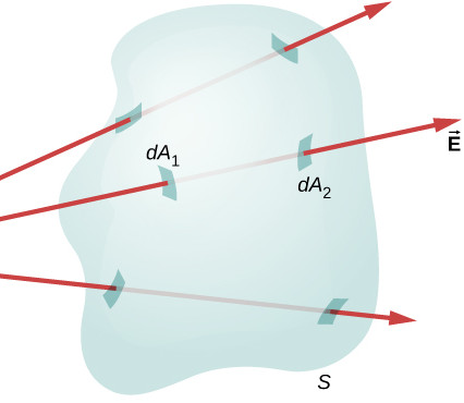 [Based on OpenStax, Chapter 6, Questions 3 and 4] The figure on the right shows an arrangement in which net flux through a closed surface is zero. Answer the following questions: (a) Is the net flux through a closed surface always zero? If yes, explain why. If no, explain in what arrangement net flux through a closed surface is not zero. (b) An open surface is a surface that is bounded by a closed loop (like a small piece taken out of a plane; a piece of paper is an example of open surface). Can the net flux through an open surface placed in a region of non-zero electric field be zero? If not, explain why not. If yes, explain in what arrangement net flux through an open surface is zero.
A1 – “Net flux through closed and open surfaces”: (a) The net flux through a closed surface is not always zero, but in order for non-zero net flux to pass through a closed surface, the surface must enclose a net charge (the figure shows a charge placed outside of the closed surface). (b) A net flux through an open surface can be zero. The simplest such arrangement is a flat open surface placed in a region of uniform electric field oriented in a way, so that the surface is parallel to the electric field (that is, the surface normal is perpendicular to the electric field,  ).
).
Q2 – [Based on OpenStax, Chapter 6, Question 7] If the electric flux through a closed surface is zero … :
(a) Is the electric field necessarily zero at all points on the surface?
(b) Can there be electric charges present within the surface?
(c) What is the net charge inside the surface?
(d) What, if any, are the constraints on what charges can be present outside the surface?
A2 – “Electric flux, field, and charges (subtleties in their relationships)”: (a) With the zero net flux, the electric field on the closed surface is not necessarily zero. For example, for a portion of the surface, the flux may be positive (outward net electric field), while in the other portion of the surface, the flux is negative (inward net electric field). This would be the case for a surface that encloses a dipole (an arrangement of equal positive and negative charge. (b) The question is a bit vague—there can be electric charges (positive and negative), but there can’t be a net electric charge inside the closed surface. (c) The net charge inside the surface must be zero (this is what Gauss’s Law says, and, as a fundamental law of nature, it is always true). (d) There are not constraints on what charges may be present outside the surface. There may be no charges outside the surface, there may be any amount of charge in any configuration—outside the closed surface. According to Gauss’s Law, the net flux through a closed surface is only affected by the charges enclosed.
Q3 – [Based on OpenStax, Chapter 6, Question 8] Gauss’s Law and Coulomb’s Law (the  dependence of electric field) are closely related, as they imply each other (in logic/derivation/proof sense): Gauss’s Law implies Coulomb’s Law, and Coulomb’s Law implies Gauss’s Law. In particle physics, there are forces (and fields associated with these forces) which do not vary as , but instead as
  . (On top of the inverse-square decrease, there is an exponential decay with length scale
  .) Answer the following two questions: (a) For such a field, would there be a law like Gauss’s Law? Explain why or why not. (b) How would net flux through a closed surface containing a “charge” producing such a field change, as this closed surface becomes (i) smaller or (ii) larger (either more tightly enclosing the “charge” or more loosely enclosing the “charge”)? Explain.
A3 – “Gauss’s Law for a hypothetical short-range force”: (a) For such a field, Gauss’s Law would not hold. For example, if the enclosing surface is very large, the net flux through the surface may be zero (or more precisely, asymptotically approach zero) even though the surface closes a net charge. The difference comes down to this: for inverse-square forces, as the diameter of the enclosing surface increases, the changes in the surface area and the field strength cancel out (the field decreases as and the surface area increases as  ). With the exponential decay on top of that, the product of field times the surface area is no longer constant as a function of size of the enclosing surface. (b) As explained in (a), as the “charge” is more loosely enclosed, the net flux would decrease. But as the “charge” is more tightly enclosed, the net flux will depend only on the amount of charge enclosed, not on the size of the closed surface (so you get something like the Gauss’s Law). As
  , the exponential factor
  , meaning, for distance much less than , the force would behave as an inverse-square force.
Q4 – [OpenStax, Chapter 6, Question 14] Explain the role that symmetry plays in the application of Gauss’s Law. There are only 3 examples of symmetries in which Gauss’s Law can be used to derive electric field. Give all 3 examples of continuous charge distributions (naming the symmetry they exhibit) in which Gauss’s Law is useful in determining the electric field.
A4 – “Symmetry and finding electric field with Gauss’s Law“: The key role symmetry plays is, it allows you to factor the electric field outside of the integral, either by arguing that the electric field is uniform over the surface (so it gets factored out as a constant factor), or because  is zero (this is the case for portions of the closed Gaussian surface for cylindrical and rectangular geometries), allowing you to argue that the integral is zero. The three types of charge distributions in which these symmetry arguments can be made are: (i) spherically symmetric charge distributions (charge density is only a function of radial distance r), (ii) cylindrically symmetric charge distributions (charge density is constant with respect to one of the axes, e.g. z, and it is only function of radial distance r from this axis), and (iii) charge distributions with planar symmetry (charge density is constant with respect to two axes, e.g. x and y, leaving it only as a function of one coordinate variable, z).
Q5 – [OpenStax, Chapter 6, Question 18] A charge q is placed in the cavity of a conductor as shown on right. Will a charge outside the conductor (that is, outside the outer surface of the conductor) experience an electric field due to the presence of q? Explain why or why not (describe in detail any other charges that are induced due to the presence of q).
A5 – “Charge placed in a cavity inside conductor”: Yes, a charge outside the conductor will experience an electric field due to the presence of q. This is how. Because the surface S lies inside the conductor, the net flux through S is zero (electric field on that Gaussian surface is always zero). So it must enclose zero net charge, and since it already encloses +q, that means there must be induced negative change equal in magnitude to q on the inner surface of the conductor. Assuming the conductor is electrically neutral (if it is not, then there is an offset for the charge amounts we discuss here), there must be a(n additional) charge of +q on the outer surface of the conductor, which produces electric fields outside the conductor, which can be felt by a test charge placed on the outside.
Electric Potential and Capacitors (questions and model answers)
Where applicable, assume that  .
.
Q1 – [OpenStax, Chapter 7, Questions 4 and 5 ] (a) Describe the relationship between the electric potential difference and electric field strength. Use examples if they are helpful. (b) What is the strength of the electric field in a region where the electric potential is constant? Explain your answer.
A1 – “Electric potential and electric field”: The key relationship between electric potential ( ) and electric field (
 ) to remember is this relationship:
  (or, in the 1-dimensional version,
  ). The following answers are application of this relationship.
(a) Beyond the equations above, some word descriptions you can use to describe the relationship are (I am omitting the “minus sign” here for the sake of brevity): “electric field is rate of change of electric potential, as a function of position”, “electric field is the slope of  curve”, and “electric field is given by the electric potential difference, divided by the distance.” (b) Because of this relationship, in a region where electric potential is uniform, electric field is zero (the position derivative is zero).
Q2 – [OpenStax, Chapter 7, Questions 6 and 9] (a) If a proton is released from rest in an electric field, will it move in the direction of increasing or decreasing electric potential? How about if an electron is released? A neutron? Explain why. [Note carefully the difference between “electric potential” and “electric potential energy.] (b) What is the relationship between voltage and energy, that is, the relationship between electric potential and energy?
A2 – “Electric potential and electric potential energy”: All things tend to move towards lower potential energy, because in the absence of other forces, the conservative force (in this case, electrostatic force) will push the object from position of higher potential energy to lower potential energy. The key in answering this question is to understand the relationship between electric potential () and electric potential energy ( ).
).
(a) A proton has a positive charge ( ), so the change of electric potential and electric potential energy are in the same direction. Since the proton is pushed in the direction of decreasing electric potential energy, that means the proton is also pushed in the direction of decreasing electric potential. For an electron, since it has a negative charge (
 ), the direction of the change of electric potential and electric potential energy are reverse. When an electron moves from lower electric potential to a higher electric potential, its electric potential energy decreases (it becomes more negative, for example), so an electron will be pushed in the direction of higher electric potential. Since neutron has no electric charge (
 ), it does not feel an electric force and is not moved in either direction (there can be an induced electric dipole moment, but that involves a higher-order correction term than what we are considering here). (b) The relationship between voltage and energy is what we said above:
  , where we are talking about potential energy of a charge (
 ) moving through electric potential change
  .
.
Q3 – [Based on OpenStax, Chapter 7, Question 15] (a) For a uniformly charged sphere, describe how its electric potential compares to that of a point charge (of the same amount of charge). Explain where its electric potential differs to that of a point charge and how. (b) For a uniformly charged spherical shell, describe how its electric potential compares to that of a point charge (of the same amount of charge). Explain where its electric potential differs to that of a point charge and how.
A3 – “Electric potential of spherical charge distributions”: Two things are good to know: (1) by convention,  , and (2) the electric fields of different spherical charge distributions (
 for outside the sphere, and inside,
  and
and  ). With these, you can find the electric potential by integration of
  .
.
(a) Outside the sphere, the electric potential of a spherical charge distribution is the same as the electric potential of a point charge (carrying the same total charge). Inside the sphere, the electric potential does not increase as quickly as it does for a point charge, since instead of  increasing as , decreases proportionally to
  as . Electric potential is still at a maximum at the center of the sphere. (b) For a uniformly charged spherical shell, since the electric field goes to zero inside the shell, the electric potential inside the shell is constant, at the value,
  , where
  is the radius of the spherical shell.
Q4 – [OpenStax, Chapter 7, Questions 20 and 23] (a) Suppose you have a map of equipotential surfaces spaced 1.0 V apart. What do the distances between the surfaces in a particular region tell you about the strength of the electric field vector () in that region? [Bonus: Can the map of equipotential surfaces tell you the direction of ?] (b) Can a positively charged conductor be at a negative electric potential? Explain what it would take.
A4 – “Equipotential surfaces and conductors“: (a) With a map of equipotential surfaces spaced 1.0 V apart, since each neighboring surface is at a constant apart, closer spacing (smaller  ) indicates a larger electric field. A topographic map provides a nice analogy in the context of gravitational potential energy. [Bonus material: Yes, the equipotential surfaces can tell you the direction of . The electric field points perpendicular to the equipotential surface, directed in the direction in which electric potential decreases. These restrictions pick out one unique direction, which is the direction of the electric field.] (b) A positively charged conductor can be at a “negative” potential, but this would require a rather unusual reference. For example, if you define
  , then for a small enough positive charge (on a spherical conductor of large enough radius, for example), the conductor will be at a negative potential, since the positive charge won’t have raised electric potential at the surface sufficiently above
  to make the value positive. If this sounds too artificial, another, more realistic way to have a positively charged conductor at a negative potential is by placing it inside the cavity of a negatively charged conductor—imagine two concentric spherical shells of conductors, where the outer shell carries enough negative charge.
Q5 – [OpenStax, Chapter 8, Questions 1 and 3] (a) Does the capacitance of a device depend on the applied voltage? Does the capacitance of a device depend on the charge residing on it? (b) Evaluate whether this statement is true: “The value of the capacitance is zero—or undefined—if the plates are not charged.” Explain your answer.
A5 – “Capacitance”: Although capacitance is defined as  , it’s important to understand that voltage between the capacitor plates will depend on charge , always in such a way that -dependence always cancels out and capacitance
  only depends on geometric and material properties.
(a) So, the capacitance of a device does not depend on the applied voltage or the charge on the device. It is a constant quantity that can be treated as the property of the device. (b) Even if the plates (of a parallel-plate capacitor) are not charged, the capacitance has a definite value—it is neither 0 nor undefined (don’t be fooled by the superficial appearance of “dividing 0 by 0”, if you are looking at ; instead, think of it like  ).
).
Q6 – [OpenStax, Chapter 8, Questions 2 and 10] (a) Would you place the plates of a parallel-plate capacitor closer together or farther apart to increase their capacitance? (b) As you change the distance between capacitor plates, how does the energy stored in the capacitor change? If insufficient information is provided to answer this question, explain what information is necessary and why. (c) How does the energy stored in an air-gap capacitor change when a dielectric is inserted (i) if the capacitor is isolated so that its free charge does not change, and (ii) if the capacitor remains connected to a battery, so that the potential difference between its plates is kept constant.
A6 – “Capacitance and Energy”: Two things are useful to know here: (1) Formula for capacitance of parallel-plate capacitors,  , where
  is the area of the plates and
  is the separation between the plates; for vacuum capacitor,
  (otherwise it is a property of the dielectric). (2) Formulas for energy stored in a capacitor:
  (all three expressions are useful at different times).
(a) To increase the capacitance of the parallel-plate capacitor, the plates should be moved closer (decrease ). (b) There is insufficient information provided here. With changing capacitance (), charge on the plate or the voltage between the plate (or both) must change, and without knowing which quantity is held constant, you can’t know the change in energy stored. If the voltage is held constant (connected to battery), then decreasing the distance (increasing the capacitance) increases the energy stored. If the charge is held constant (isolated from battery), then increasing the distance (decreasing the capacitance) increases the energy stored. (c) When a dielectric is inserted, the value of  increases, increasing the capacitance. So, (i) if the capacitor is isolated (constant charge), the energy stored decreases. (ii) But if the capacitor is connected to a battery (constant voltage), the energy stored increases.
Circuits (questions and model answers)
Q1 – [OpenStax, Chapter 10, Question 1] What is the “internal resistance” of a battery? Describe the internal resistance in your own words, and especially explain how it affects operation of a battery and realistic analysis of a circuit containing the battery.
A1 – “Internal resistance of battery”: Internal resistance is a way to model real-world voltage sources. An ideal voltage source (battery) would be able to provide an infinite amount of current ( , and as resistance goes to zero, current goes to infinity), but this is not true of any real-world voltage sources. A way to model the real-world voltage sources that includes this restriction is by including an “internal resistance” () which is in series with the ideal voltage source. With this inclusion, the maximum current from the voltage source is
  . The open-circuit voltage (i.e. voltage read at the terminals when the battery outputs zero current) is still equal to , but as the battery sources more and more current, the terminal voltage falls, according to
  .
.
Q2 – Consider two resistors, R1 and R2, being placed in a circuit. Consider the equivalent resistance Req of the resistors and compare it to each resistance if (a) the resistors are placed in a series configuration, or if (b) the resistors are placed in a parallel configuration. Specifically, say if Req is greater/smaller than each resistance or if it depends on other circumstances.
A2 – “Combining resistors in series or parallel”: (a) So, the formula says  for series combination. Here is something you can get immediately from this expression: the equivalent resistance is guaranteed to be greater than either of the two resistances being added in series (
 ). This should make sense from our understanding of how resistance is related to resistivity (
 ). Adding resistors in series effectively makes the length longer, resulting in greater resistance. (b) For parallel combination, the formula says
  ; the intuitive feel is easier to get from the following re-written expression:
  . The last two expressions show that the equivalent resistance is guaranteed to be smaller than either of the two resistances (
 on the r.h.s., you see each of the two resistances being divided by a number greater than 1). This should also make sense from our understanding of resistance. With parallel resistors, you are adding additional paths (or effectively increasing the cross-sectional area ), so adding resistors in parallel would decrease their resistance.
Q3 – [OpenStax, Chapter 10, Question 9] Consider the circuit shown below. Does the analysis of the circuit require an application of the Kirchhoff’s rules, or can it be re-drawn with equivalent resistances to simplify the circuit? If it can be simplified without using Kirchhoff’s rules, describe each step of simplification (the total equivalent resistance may be given, but it is optional; the description of steps is required).
A3 – “Circuit Analysis”: (Figure reproduced on right.) This circuit can be simplified (without using Kirchhoff’s rules) by considering resistors in series/parallel step by step. Following are the steps: (1) Add R3 and R5 in series (R35). (2) Add R4 and R35 in parallel (R345). (3) Add R2 and R345 in series (R2345). (4) Add R2345, R1, and R6 in parallel. (The algebraic final result is rather complicated, so I won’t write it down.)
Q4 – The two main measuring devices in circuit analysis are voltmeters and ammeters. Describe and/or explain, (a) what they measure, (b) how they are connected in a circuit to measure these quantities, and (c) what their ideal internal resistances are and why.
A4 – “Voltmeters and Ammeters“: (a) Voltmeters measure voltage (kinda obvious), and ammeters measure current (it is an “amp-meter”, or “ampere-meter”). (b) Voltmeter has to be connected in parallel (it measures voltage difference between its two probes), and ammeter has to be connected in series (it measures current that goes through the meter, entering through one probe and exiting through the other probe). (c) An ideal voltmeter has infinite internal resistance, so that when it is connected in parallel, it does not modify the circuit it is measuring (and if it is mistakenly connected in series, it would turn the circuit into an open circuit); an ideal ammeter has zero internal resistance, so that when it is connected in series, it does not present any additional resistance to the current (and connecting an ammeter in parallel amounts to shorting the two points that its probes touch).
Q5 – In a given circuit, can you categorically say that replacing a resistor with a smaller resistor (or a greater resistor) will result in smaller/greater dissipation of energy? If yes, explain why. If not, explain also why not, and give specific examples that illustrate your assertion.
A5 – “Power dissipation in circuit as a function of resistance”: You cannot categorically say how the power dissipated in circuit ( ) would change as the resistance varies. Because of Ohm’s Law (
 ) if resistance varies, at least one of the two, voltage or current, has to change. Depending on how the voltage and current changes, with decreased resistance, the power consumed may increase (for example, if voltage is constant (i.e. connected to battery),
  says that power consumed increases), and the power consumed may decrease (for example, if current is constant (i.e. connected to a “current source”),
  says that power consumed decreases).
Magnetism Intro (questions and model answers)
Q1 – [OpenStax, Chapter 11, Question 1] Both electric fields and magnetic fields can exert a force on a moving electric charge. Compare and contrast the electric force and magnetic force on a moving electric charge. Specifically, bring up at least 2 points of commonality and 2 points of difference between the two types of force.
A1 – “Compare/Contrast electric force and magnetic force”: [COMPARE] In both cases, the fields are defined in a way that they relate directly to the forces exerted. Specifically, the magnitude of the electric/magnetic force is proportional to the magnitude of electric/magnetic field at the location of the charge. Also, surprisingly, both forces (electric and magnetic) are directly proportional to the electric charge (“magnetic charge” always being zero). [CONTRAST] Electric force only depends on the electric charge and electric field (that is, if you have an electric field that is only a function of position, electric force is also only a function of position). Magnetic force, however, depends on the velocity of the electric charge also. Also, electric force is parallel (or antiparallel, for negative charges) to the electric field; the magnetic force is perpendicular to the magnetic field and the velocity of the charge. [ASIDE] If you remember the statement “Conservative forces are forces that only depend on position,” you might wonder if magnetic force may be non-conservative, since it depends on velocity as well as (possibly) on position. It turns out that static magnetic fields do not produce magnetic forces that do any work, because magnetic force is always perpendicular to the velocity (so the dot product of force and displacement is zero).
Q2 – [OpenStax, Chapter 11, Question 2] Answer these questions: (a) Is it possible for the magnetic force on a charge moving in a non-zero magnetic field to be zero? (b) Is it possible for the electric force on a charge moving in a non-zero electric field to be zero? (c) What is necessary for the net force due to electric field and magnetic field to be zero, on a charge moving through a region of non-zero electric and magnetic fields? If it helps, describe a specific arrangement (and if possible, comment which features of this arrangement would need to be generally true, for any arrangement leading to zero net force on the charge).
A2 – “Electric/Magnetic Fields and Electric/Magnetic Forces”: (a) Yes. If the charge is moving parallel to the magnetic field, then  in the Lorentz force equation is zero, since
  , where
  is the angle between the velocity and magnetic field. (b) No. Since electric force (
 ) is given by scalar multiplication () of the electric field (, as in
  ), unless the charge or the electric field is zero, electric force is non-zero. (c) Since the electric force won’t be zero, the magnetic force must balance out the electric force. The only way this can happen is if magnetic field and the particle velocity are perpendicular to the electric field, so that directly opposes the electric field . This arrangement is referred to as “crossed fields” and some devices (such as mass spectrometer) use this to select particular velocities of particles.
Q3 – [OpenStax, Chapter 11, Question 9] Considering the magnetic force law, are the velocity and magnetic field always perpendicular? Are the force and velocity always perpendicular? Are the magnetic force and the magnetic field always perpendicular? In any case where they are not, give a counter-example.
A3 – “Interpreting  “: No, the velocity and magnetic field are not always perpendicular (it is useful to decompose velocity into component that is parallel to the magnetic field and component that is perpendicular to the magnetic field; the component that is parallel to the magnetic field will remain constant for a charge particle moving in a magnetic field only). Yes, magnetic force and velocity are always perpendicular (property of cross product). Yes, magnetic force and magnetic field are always perpendicular (also property of cross product; this is why component of velocity parallel to magnetic field won’t change, since acceleration is always perpendicular to the magnetic field).
Q4 – [OpenStax, Chapter 11, Question 13] CHALLENGE QUESTION: Hall potentials are much larger for poor conductors than for good conductors. Why? (Hint: Start with Eq. 11.30, which describes the Hall potential. Consider how the parameters determining Hall potential may differ between good and poor conductors; it may be helpful to review Sections 9.2 and 9.3.)
A4 – “Hall Potential for Poor Conductors“: It comes down to the matter of this question: what is the drift velocity of charge carriers? Since the charges come to an equilibrium state in the Hall effect experiment when  (that is, the “effective electric field” due to magnetic field and drift velocity is equal in magnitude to the electric field due to the charge separation, so the forces due to each can balance out), in whichever material drift velocity is higher, Hall potential will be greater. Counter-intuitively, for the same amount of current, drift velocity is higher in material with lower conductivity. According to our model of conduction, the current density is
  . For many types of poor conductors (especially semi-conductors), what limits their conductivity is low value of free charge density
  . So for the same value of current density
  , the drift velocity
  has to be higher for each charge carrier and this leads to a larger Hall potential.
Sources of Magnetic Fields (questions and model answers)
Q1 – [OpenStax, Chapter 12, Question 6] Compare (that is, point out the commonalities of) and contrast (that is, point out the differences between) the electric field of an infinite line of charge and the magnetic field of an infinite line of current.
A1 – “Compare/Contrast line-charge electric fields and line-current magnetic fields”: Other valid comparisons/contrasts are possible; below are some key examples.
[COMPARE] In both cases, the field decreases with distance as  . Electric field of an infinitely long line of charge of linear density is given by
  ; magnetic field of an infinitely long current
  is given by
  . This is consistent with both magnetism and electricity being “inverse square” laws. For similar geometries, both electric fields and magnetic fields have similar distance relationships.
[CONTRAST] The directions are different. Electric fields point radially (away, for positive ) from the line of charges; magnetic fields trace out concentric circles, with the line of current going through the center of the circle. The direction of the circular field lines is given by the right-hand rule.
In addition, there is the usual distinction between electric fields and magnetic fields: electric fields point in the direction along the electric force; the relationship between magnetic force and magnetic fields is given by  (this results in magnetic force that is perpendicular to the magnetic field).
Q2 – By the end of Chapter 12, you have seen a few different versions of the “right-hand rule.” Describe three (3) of them and give an example where it can be used. [Note: Two of the versions are explicitly named as “RHR” with a version number in the textbook; others may be found as you read through the textbook. I also cover these in lectures.]
A2 – “Right-Hand Rules”: Below two figures illustrate the first two versions of the right-hand rule. From Fig. 11.4 and Fig. 12.6:
A description of the third version is given in Section 12.6, discussing Equation 12.28: “You can find the direction of  with a right-hand rule: Curl your fingers in the direction of the current, and your thumb points along the magnetic field in the interior of the solenoid.” This version interchanges the role of the current and the role of the magnetic field, as compared to the RHR-2 shown above—and it all seems to work out, as long as you use your right hand and carefully lay out the limitations when the rule can be used. The fundamental rule remains RHR-1, which gives the direction of the cross product (e.g.
  ).
).
Q3 – Magnetic fields are given in units of “tesla” ( , among others). In this unit, give a few typical values of magnetic fields: (a) What is considered a moderate value of magnetic field (give an example and strength in tesla)? (b) What is considered a very large value of magnetic field (give an example of source and strength in tesla)? (c) What is considered a small (but non-zero) value of magnetic field (give an example and strength in tesla)?
A3 – “Magnetic field ranges”: Many different examples can be given here (this is a “number sense” exercise where the value is in your having seen the examples of “reasonable” magnetic field values). For a more comprehensive survey than the minimal examples given here, see this Wikipedia page, Orders of magnitude (magnetic field).
- An example of “moderate value” would be the geomagnetic field (in some sense, “the most common” magnetic field around humans), which measures at about 10-4 tesla.
- There is much room for interpretation for “very large value.” In terms of magnetic fields we can produce in lab, about 50 tesla is the maximum constant magnetic field we can produce (using the state-of-the-art superconductor magnets). In most experiments, obtaining magnetic fields larger than 10 tesla takes a great deal of effort (and equipment). Larger magnetic fields are estimated for certain astronomical phenomena (and other physical interactions; see page above).
- As with (b), there is room for interpretation. In terms of detection threshold, “a very small magnetic field” of around 10 femtotesla can be measured with state-of-the-art magnetometers (SQUID and atomic magnetometers are two close competitors). Everyday magnetic noise (for example, from a BART train passing by, for most locations in the Bay Area) ranges around 10-7 tesla (or about 1 milligauss).
Q4 – (a) Name and describe the three (3) types of magnetism exhibited by materials. (b) If real-world materials can be modeled by current loops (a very bad model in most cases, but that’s the setup of this question), what type of magnetism will these model materials exhibit? Explain your answer.
A4 – “Three types of magnetism; Conducting loop model“:
(a) There are three types given in Section 12.7: paramagnetism, diamagnetism, and ferromagnetism. They are distinguished by the direction of induced magnetic dipole and its strength. In paramagnetism, the induced magnetic dipole (and the field due to induced magnetic dipole) points in the same direction as the applied external magnetic field. The same direction is the case for ferromagnetism as well, but the magnitude of the induced dipole is much larger for ferromagnetic materials than paramagnetic materials (this is explained with “magnetic domain”; there is much more material here that we won’t get into). In diamagnetism, the induced magnetic dipole points in the opposite direction as the applied external magnetic field.
(b) Looking at Figure 11.15 in Section 11.5 gives some sense of how the current carrying loop would become aligned in an applied magnetic field.
From the position in (a), the loop will rotate counterclockwise (imagine a viewpoint where permanent N pole is directly to the left and permanent S pole is directly to the right). When the loop settles in that position (note that (b) is showing the picture after the commutator flipped the direction of current; ignore (b) picture), the magnetic field due to the current in the loop points to the right (apply the third version of right-hand rule to see for yourself). This is the same direction as the magnetic field due to the permanent magnets, so the current loop is exhibiting a paramagnetic behavior.
Faraday’s Law (questions and model answers)
Q1 – [Modified from OpenStax, Chapter 13, Question 5] Consider the following demonstration of eddy current using a neodymium magnet, plastic pipe, and aluminum pipe (the relevant portion of the demonstration ends around 2:12, although you are welcome to watch the whole video).
Answer the following two questions: (a) With the magnetic field changing as the magnet drops, does the induced voltage around the pipe depend on the resistivity of the pipe material? (b) Does the induced current (eddy current) depend on the resistivity of the pipe material? Give brief explanations for your answers.
A1 – “Induced voltage and induced current”: The answers here are based on Faraday’s Law ( ) and Ohm’s Law ().
(a) Based on Faraday’s Law, induced voltage does not depend on anything other than the change of magnetic flux itself (see how in the equation there is no term other than  , which is
  , and the rate of change of magnetic flux). At a given speed of the magnet, the voltage induced around the pipe while it falls down the aluminum pipe is the same as while it falls down the plastic pipe (for that matter, it would be the same around the air along the same path, if the magnet was just falling in air).
(b) The drastic difference between the two pipe materials come from Ohm’s Law. Given the same induced voltage (or rather, same-ish, because ultimately the magnet velocity is not the same between the two), amount of current produced depends on the resistance along the path. Smaller resistance leads to larger current, which generates a larger magnetic field that opposes the motion of the magnet more strongly (i.e. what you see with aluminum pipe).
Q2 – [Modified from OpenStax, Chapter 13, Question 11] The circular conducting loops shown in the figure below are parallel to each other, oriented perpendicular to the plane of the page. When the switch S is closed, current flowing through loop C will point out of the page at the top of the loop and point into the page at the bottom of the loop.
Answer the following questions:
(a) When the switch S is closed, what is the direction of the current induced in D?
(b) A long time after the switch S is closed, describe the current (if any) flowing in the loop D.
(c) Will any current flow in the loop D when the switch is opened (after some time of the switch being closed)? If so, what is the direction of the current induced in D? Give brief explanations for your answers.
A2 – “Faraday’s Law/Lenz’s Law Application”: We use Faraday’s Law () and Lenz’s Law (the verbal description of the negative sign in Faraday’s Law: current induced by change in magnetic flux points in a direction so that magnetic field due to induced current opposes the initial change) to answer these questions.
(a) As the switch S is closed, current flows through loop C in the counterclockwise direction as viewed from the right (looking at the C loop through/past D loop). (Applying the right-hand rule) This current produces magnetic field that points to the right in the diagram (or viewing from the right, points towards the viewer). Since magnetic field is increasing from 0, the change of magnetic field is in the same direction, so the magnetic field due to induced current should point left (or viewing from the right, away from the viewer), in order to oppose this change. The direction of current induced in D that will give this direction of magnetic field is clockwise as viewed from right (i.e. in the opposite direction as the direction of current in C).
(b) A long time after the switch S is closed, as a steady current flows through loop C, no current flows in the loop D (if the loop D has some resistance, which is the case unless it’s a superconducting loop). Because the induced voltage is due to changing magnetic flux, if there is no change in magnetic field/flux, there is no induced voltage.
(c) As the switch S is opened, the magnetic field due to loop C changes from pointing to the right (see (a) above) to being 0. The change amounts to the leftward change of magnetic flux, so a current is induced in loop D that will produce a magnetic field pointing to the right. This current points in the counterclockwise direction as viewed from the right (same perspective as in (a), describing the original direction of current in loop C).
Q3 – [Modified from OpenStax, Chapter 13, Question 12] Consider a bar magnet moving toward a copper loop, as shown below.
Answer the questions below, using the perspective of looking at the loop from the top, above the magnet (the S pole end of the magnet), looking down towards the magnet and the loop:
- As the magnet approaches the loop, will the induced voltage produce a current that circulates clockwise or counterclockwise?
- After the magnet passes through the loop (and moves away), will the induced voltage produce a current that circulates clockwise or counterclockwise?
- Imagine, instead of a copper loop, the loop is made of a superconducting material, so that if a current is started in the loop, no applied voltage is needed to maintain the current. Rather, a voltage applied in the opposite direction is needed to stop the current. After the magnet passes through such superconducting loop, what is the direction of the “net current,” if any, flowing in the loop?
- For the same superconducting loop in (c), imagine, instead of a bar magnet (a magnetic dipole), we have a magnetic monopole (for example, just the north pole) possing through the loop. After the monopole passes through such superconducting loop, what is the direction of the “net current,” if any, flowing in the loop? [Note: For this question, you will first have to imagine the magnetic field lines of a magnetic monopole. Assume that the magnetic field lines of north monopole looks the same as the electric field lines of a positive charge.]
A3 – “Current induced in a loop”: The dipole (bar) magnet produces magnetic field which points down into the loop whose strength decreases with distance from the magnet. Consider the picture carefully and convince yourself that this is true both before the N pole passes through the loop and after the S pole passes through the loop, with the whole magnet on the other side.
- We have an increasing magnetic field that points into the loop, so the change in magnetic flux points into the loop. Using Lenz’s Law, the current induced by this change in magnetic flux should produce a magnetic field pointing out of the loop, so the induced voltage will “go” in counterclockwise direction.
- We have a decreasing magnetic field that points into the loop, so the change in magnetic flux points out of the loop. Using Lenz’s Law, the current induced by this change in magnetic flux should produce a magnetic field pointing into the loop, so the induced voltage will “go” in clockwise direction (yes, opposite from (a) above).
- We can consider this picture symmetrically: what we have as the magnet approaches the loop is the same picture (in terms of
 ) as what we have as the magnet moves away from the loop, having passed through. The only thing that changes is the direction (as you saw in (a) and (b) above), which means if we add up all the contributions to the current induced (increasing/decreasing it), they add up to zero. There should not be any leftover “net current” flowing in the loop, after the dipole magnet passes through.
 - With a monopole magnet (i.e. “magnetic charge”), a key thing changes. At the start, we said, “The dipole (bar) magnet produces magnetic field which points down into the loop whose strength decreases with distance from the magnet.” With a monopole magnet, this statement needs to be changed into “The monopole magnet produces magnetic field which decreases with distance from the magnet. When the magnet is above the loop, the magnetic field points down into the loop; when the magnet is below the loop, the magnetic field points up out of the loop.” The qualitative features in (a) do not change (same directions of everything), but the answer to (b) changes: after the magnet has passed through the loop, the change in magnetic flux still points into the loop, because it is a decreasing magnetic field which points out of the loop, so the induced current still points counterclockwise after the magnet passes the loop. Since all contributions to the induced current is in the counterclockwise direction, there will be a “net current” after the magnetic monopole passes through the loop. (This setup, schematically, is the setup that produced a signal that hints at existence of magnetic monopole in the 80s. Unfortunately, the result has not been reproduced since.)
Q4 – [OpenStax, Chapter 13, Question 22] Electromagnetic braking can be achieved by applying a strong magnetic field to a spinning metal disk attached to a shaft. (a) Explain how this braking mechanism works. How does the magnetic field slow the spinning of the disk? (b) Explain why the spinning disk needs to be metal for this to work. Why would the brakes not work if the disk was made of plastic instead of metal?
A4 – “Electromagnetic Braking“: It is important to note that the applied magnetic field should be nonuniform, so that as the disk spins, a given region of the disk experiences a magnetic field that changes over time.
(a) This changing magnetic field produces eddy current in the metal disk. There are two different aspects you can consider which shows how the eddy current would slow down the metal disk: (i) Given that the metal disk has some resistance, the current flowing in the disk generates heat (according to the Joule heating formula,  ) and this leads to dissipation of mechanical energy. (ii) The direction of the eddy current (as determined through Lenz’s Law) produces magnetic field which will push/pull on the magnet in the direction opposite to the spinning direction, resulting in slowing down of the spinning disk (… to be completely rigorous here, it would be the reaction force to the push/pull on the magnet that slows down the disk, as the force on the magnet itself does not affect the disk but reaction force by the magnet on the disk will; or you can instead consider force due to the magnet on the magnetic dipole of the eddy current; however you analyze it, the end result should agree with (i) before).
(b) If the spinning disk is plastic, while the induced voltage would not change (Faraday’s Law still holds), this voltage would not produce any current (plastic has effectively infinite resistance). Without an induced current, there is no further interaction and no dissipation of mechanical energy.
Time-Dependent Circuits (questions and model answers)
Q1 – Capacitors play a certain role in time-dependent circuits that make the circuit time-dependent and behave over time in certain ways. This role is summarized mathematically by the definition of capacitance, , or re-written in terms of the voltage change across the capacitor,  . Explain, qualitatively, what effect presence of capacitor has on voltages and currents in a time-dependent circuit.
A1 – “Role of capacitors”: In short, “capacitors prevent sudden change in the voltage across them.” It takes a two-step argument. The voltage across a capacitor is given by (so voltage across a capacitor is proportional to charge stored ). The rate at which charge stored on a capacitor changes is given by the current  , and since the amount of current is finite (at least for a realistic circuit), the rate at which changes (and hence the rate at which changes) can only be finite.
Sometimes this is “enforced” by a capacitor acting like a short (this would be when the capacitor starts out uncharged, with ; when voltage/current is suddenly applied, the voltage across the capacitor remains at  , as it would be for a short); other times this results in capacitor providing voltage when the original voltage source is removed (as in capacitor discharging over time).
Q2 – Inductors play a certain role in time-dependent circuits that make the circuit time-dependent and behave over time in certain ways. This role is summarized mathematically by the definition of inductance,  , or re-written in terms of the voltage induced over the inductor,
  . Explain, qualitatively, what effect presence of inductor has on voltages and currents in a time-dependent circuit.
A2 – “Role of inductors”: In short, “inductors prevent sudden change in the current through them.” It is evident from the defining equation for inductors, . Because the rate of current change is tied to the voltage induced across the inductor, current through inductor cannot change suddenly without inducing a large voltage across it (the most extreme example of this is the phenomenon of arcing, which happens when an inductor—a motor or a solenoid—forces current through open circuit by inducing a large enough voltage, when the switch tries to cut off the current suddenly). This can be useful in filtering out high-frequency noise (one of the ways ferrite beads work is by increasing inductance of the portion of the wire where they are placed, functioning as a sort of inductor).
Q3 – The parameters  (product of resistance and capacitance, for a resistor and a capacitor in a circuit in certain arrangements) and
  (inductance divided by resistance, for an inductor and a resistor in a circuit in certain arrangements) play important role in characterizing time-dependent circuits and are sometimes the given the name “time constant.” (a) Explain what this “time constant” characterizes with a relevant example. (b) Work out the units of (“ohm times farad”) and show that it has a unit of time. (c) Work out the units of (“henry divided by ohm”) and show that it has a unit of time.
A3 – “Time constants, RC and L/R”: In a very qualitative sense, “time constant” can be described as the amount of time in which substantial amount of change occurs.
(a) In a more quantitative sense, as time constants occur in cases of a discharging/charging circuit, it gives the amount of time in which certain amount of change occurs. For example, in a discharging circuit for a capacitor, voltage across the capacitor may be described as following,  . In looking at this expression, from
  (
( ) when
  , the voltage changes to
  , or since
  (it’s closer to 2.7 but 3 is easier to remember/eyeball), the time constant RC is the amount of time for the capacitor to discharge down to 1/3 of its initial voltage/charge. For another example, in a charging circuit for a capacitor, the voltage across the capacitor may be described as,
  , where
  is the charge that the capacitor will charge up to (as
  ). At time , we have
  , or if we use
  ,
,  . It’s the amount of time needed for the capacitor to charge up to 2/3 of its eventual final charge.
(b) We will work out “ohm times farad.” While this can be done with a single Wolfram|Alpha search, the goal here (well, my goal, anyway) is to be able to do it by hand, without looking up anything. Because units in electricity and magnetism can rather be involved (there are many ways to relate ohm and farad to other units), I will invoke relevant equations to help me remember unit relationships. Resistance is given by Ohm’s Law,  , so we have “ohm” being equal to “volts per ampere”. Capacitance is defined as , so we have “farad” being equal to “coulombs per volt”. So, this gives our first simplification, as “volts per ampere” times “coulombs per volt” is equal to “coulombs per ampere” (“volts” cancel out). And since “ampere” is unit of current, or “coulombs per second”,
  , “coulombs” cancelling out.
(c) We will work out “henry per ohm”. Again, if the answer is all we wanted, a single Wolfram|Alpha search gives that; we don’t really need trained engineers and scientists for something that computers can do easily (why pay someone when it can be automated?). It’s the analytical skill involved in working out the units that we are after. The inductance is given by , which means a “henry” must be equal to  . We have from above that “ohm” is
  , so “henry per ohm” is
  . “Ampere” and “volt” cancel out, and the “1/second” in the denominator becomes simply “second” in the numerator.
Q4 – It is typical in physics classes to work with idealized objects (you may have heard of a “spherical cows in vacuum” joke). Capacitors and inductors are no exceptions; most times (and certainly in theoretical, analytical questions, all the time) we assume that we are working with ideal capacitors and ideal inductors. But in practice, there are ways in which both capacitors and inductors can be non-ideal: (a) List some of the ways in which a real capacitor may be non-ideal. (b) List some of the ways in which a real inductor may be non-ideal. (c) Considering your answer to (a) and (b), which is easier to obtain, an ideal capacitor (or at least one that is “ideal enough”) or an ideal inductor (same note here)?
A4 – “Ideal vs. Real Capacitors/Inductors“: I’ll try to be as comprehensive as I can be in the model answer here. This means the answer here will include more possibilities than I expect student answers to include (at the same time, it is probably not truly comprehensive, which means student answers may have other possibilities that I did not include here).
(a) A capacitor may be non-ideal in following ways (in order of likely—in my subjective judgment—modes of failure): (i) real capacitors have maximum rated voltage, meaning above a certain voltage, a capacitor stops working like a capacitor (this happens through dielectric breakdown); (ii) some capacitors are polarity dependent in their functioning (electrolytic capacitors are the biggest one) while ideal capacitors are not polarity dependent; (iii) there may be a small leakage current in a capacitor; (iv) capacitance may be a function of applied voltage (e.g. consider a model where distance between “parallel plates” become shorter with more charge accumulated on the plates, stronger electric force pulling them closer).
(b) An inductor may be non-ideal in following ways (in order of likely modes of failure): (i) the wires in the inductor have resistance while an ideal inductor is modeled with zero resistance; (ii) every conductor has some capacitance (see, e.g. Example 8.3 in textbook), and since inductor is made of a conductor, it should have some small capacitance; (iii) materials used in inductor (i.e. iron/ferrite core) can induce energy loss, which acts as a sort of frequency-dependent resistance (not the same thing as inductive impedance, which doesn’t result in energy loss); (iv) the inductance may be a function of current through the inductor (I’ll leave it as an exercise for you to work out the pressure that magnetic fields of a solenoid exert on the current-carrying wires of the solenoid itself; this pressure may change the geometry of the solenoid, making inductance dependent on current).
(c) When you carefully go through the list above, the one “imperfection” you can’t get away from is resistance in inductor—unless you make your inductor out of superconductor, you will always have some resistance in inductor. It becomes a question of if this resistance in inductor is significant compared to other resistances in the circuit (it may be, as you see in the LC circuit demo; with no other resistors in circuit, the 1 or 2 ohm resistance in the inductor was significant). Many of the imperfections of capacitors can be avoided with care (don’t apply too much voltage; be careful with polarities; etc.). While the imprecision in the value of capacitance is real issue, when you are building a circuit where this type of precision matters, you hand-select components (measuring component values by hand), so that you can obtain the precision needed. So, my vote would be with “ideal capacitors” being easier—or at least if I’m having a problem with a circuit I’m building, the first thing I would suspect is something imperfect about the inductor in my circuit.
AC Circuits (questions and model answers)
Q1 – [OpenStax, Chapter 15, Question 2] Explain why at high frequencies a capacitor acts as an AC short, whereas an inductor acts as an open circuit.
A1 – “High frequency behaviors of capacitor and inductor”: Note, I will be using complex impedance for all my answers. As this is not standard topic covered in lower-division physics textbook, please refer to the lectures for the introduction and explanation of complex impedance. Answers similar to my answers can be given using only the concepts and expressions introduced in the textbook.
The impedance of a capacitor is given by  . So, at high frequency (
 ), the impedance of a capacitor goes to zero (
 ), which means it behaves the same as wires do. So, a capacitor acts as an “AC short.”
The impedance of an inductor is given by  . So, at high frequency (
 ), the magnitude of an inductor’s impedance increases without limit (
 ), which means it behaves as a circuit component with infinite resistance, or an open circuit (that does not allow current to flow through).
Q2 – [OpenStax, Chapter 15, Question 6] The average AC current delivered to a circuit is zero. However, the average power dissipated in the circuit (assuming it has some resistors) is not zero. Explain why this is (conceptually if possible; using equations if necessary).
A2 – “Average power dissipated in AC circuit”: There are several ways to make sense of this result; the first two explanations below are mainly conceptual; the last explanation relies more on mathematical expressions:
(i) The AC circuit with a resistor in it can be analogized to motion of an object on a surface with friction. As the object moves back and forth (analogous to movement of charges back and forth), friction resists this motion, turning mechanical energy of the object into thermal energy (microscopically, this is exactly what happens in a resistor with moving charges).
(ii) In a resistor, the direction of voltage change and the direction of current are related, so that the current always flows from high voltage to low voltage. So, at any time, moving electrical charges in a resistor are losing electrical energy. And when the direction of current is reversed, this fact doesn’t change (because direction of voltage change is reversed at the same time).
(iii) Energy dissipated in a resistor does not depend on the direction of current (power dissipated in a resistor is ), so the fact that the current averages to zero in AC circuit is consistent with the fact that power does not average to zero, since  does not average to zero.
Q3 – [Portable T.A. Vol. 2, Chapter 44, Question 44-2] An inventor is building an electric heater. It will plug into standard American household electrical outlets, which supply an oscillating voltage of frequency 60 Hz and root-mean-square voltage  . The inventor wants the heater to contain one resistor, one capacitor, and one inductor, as drawn below.
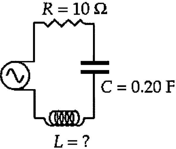
From an army surplus store, she bought a capacitor with  . Her resistor has resistance
  .
.
- In order for her device to generate as much heat as possible, what inductance should the inductor have?
- If she uses the inductor you suggested in part (a), how much heat does this device produce in 1 minute?
- Explain why commercially available heaters use only resistors, with no capacitors or inductors.
- If you plugged the inventor’s device, for one minute, into an electrical outlet that supplies at
 instead of 60 Hz, would the device generate more heat, less heat, or the same heat as you found in (b)?
A3 – “RLC Heater”: In lieu of the usual model answer, please see below excerpts from Portable T.A. [[in the course, PDF of the book was provided]] (a portion of Answer 44-1 and entirety of Answer 44-2).
First, introductory information from Answer 44-1:
Because the mathematics gets so complicated, many students have trouble following the textbook’s discussion of “forced alternating” circuits, which contain an alternating power supply, along with the usual gang of circuit elements (resistors, capacitors, inductors). As you know, I usually emphasize concepts, as opposed to rote problem-solving. Unfortunately, since introductory physics courses typically spend only a week on AC circuits, you might not have time to develop a deep understanding. You may have to rely on “canned” problem-solving procedures. I’ll present those procedures, and the accompanying intuitions (to the extent possible).
Let’s begin by writing out the most general “solution” for this kind of circuit. Then, in parts (a) through (e), we’ll see what these formulas mean physically, and how to apply them.
In alternating circuits, the power supply produces a voltage that oscillates sinusoidally. If we let  denote the power supply’s maximum voltage, then
(1)  ,
,
where  is the angular frequency, which is
  times the oscillation frequency.
The circuit elements “impede” the current. The higher the “impedance,”  , the less current flows around the circuit. Intuitively, we expect that a higher resistance leads to higher impedance. We also expect that raising the inductance increases , because the inductor opposes changes in current. The formula for confirms these intuitions:
(2)  . Impedance
As you might expect, the maximum current in the circuit is proportional to the maximum voltage, and inversely proportional to the impedance:
(3)  . Maximum current
This is the AC analog of Ohm’s law,  . But in a forced AC circuit, the current doesn’t stay at this maximum value. The power supply makes the current oscillate, at the same frequency the voltage oscillates:
(4)  , Current
where
(5)  . “Lag constant”
I’ll discuss the physical meaning of this lag factor in part (d) below. For now, let me just point out that Eqs. (2) through (5) can be combined into one monster equation. I’ll write it out, just for the record:
(2)-(5) combined ![\displaystyle i=\frac{\mathscr{E}_m}{\sqrt{R^2+(\omega L - 1/\omega C)^2}} \sin \left[\omega t - \left(\tan^{-1} \frac{\omega L - 1/\omega C}{R}\right)\right]](https://coaphys.xyz/wordpress/wp-content/ql-cache/quicklatex.com-444f53074d36e0bb720e52442a676419_l3.png "Rendered by QuickLaTeX.com") .
.
When solving problems, you should keep the equations separate, instead of combining them, to avoid getting bogged down.
With these five equations, you can find almost anything you need to know about any forced AC circuit loop. …
Now, the entirety of Answer 44-2:
In general, power is the rate of energy transfer. Here, it’s the rate at which electrical energy converts into heat energy. So, the inventor wants to maximize the power. Since
 , it follows that she wants to maximize the current through the resistor. In other words, she wants the peak current through the circuit,
  , to be as large as possible.
I see two ways of addressing this problem. We can use the forced RLC circuit formulas summarized in the previous problem. Or, we can think more physically about “resonance” in oscillating circuits. These two methods yield the same answer, because they’re really two different ways of saying the same thing. I’ll demonstrate both methods. Make sure you understand the connections between the two.
Method 1: Forced RLC equations
In analogy with Ohm’s law (
) for DC circuits, the maximum current that flows through an AC circuit is  , where denotes the impedance. So, for a given voltage, we can maximize the current by minimizing the impedance. The impedance is
 .
.To make
as small as possible for a given , the stuff inside the parentheses,  , must equal zero. Therefore, we can set
 ,
,and solve for the inductance. Since
 , we get
 .
.Method 2: Forced oscillations and resonance
Now for some intuitive physical reasoning. Imagine a kid swinging on a playground swing set. By periodically giving him a brief push, you plan to make him swing as high as possible. How often should you push? As experienced swingers will testify, you should push the kid once for every complete swing he makes. In other words, the frequency of your pushes should equal the “natural” frequency of oscillation of the swing.
This is a general property of forced (pushed) oscillatory motion. The motion achieves the highest amplitude when the push frequency matches the natural (“resonance”) frequency of the system. When the push frequency “agrees” with the system’s natural frequency, the pushes reinforce the natural motion, making the oscillations bigger than they’d otherwise be. The most dramatic example of this is the Tacoma-Narrows bridge. It collapsed partly because gusts of wind rocked it at its natural frequency. As a result, the bridge’s oscillations got bigger and bigger. Your textbook probably has a picture.
As a more mundane example, consider a block on a spring. We could attach the block to a machine that pushes it back and forth. The machine makes the block oscillate most vigorously if the machine’s “push frequency” matches the natural frequency of the block on the spring. As we saw last semester, the natural angular frequency of a block on a spring is
Block on spring

The same reasoning applies to the forced AC circuit. As discussed in question 43-7, current oscillates back and forth in an LC (or RLC) circuit, even when there’s no power supply. The circuit naturally oscillates at a certain frequency. When the same circuit gets plugged into an electrical outlet, and therefore undergoes “forced” oscillations, the oscillations are biggest when the frequency supplied by the power source matches the natural frequency of the system. Here, we can’t control the frequency of the power supply. But by choosing the “right” inductor, we can tweak the natural frequency of the circuit, so that it matches the frequency supplied by the electrical outlet. When this matching occurs, the current undergoes the largest oscillations possible. In other words, the peak current,
, becomes as large as possible.To find the natural frequency of the circuit, make an analogy with the block on a spring. Remember,
 is analogous to
  , because mass and inductance both supply “inertia” against oscillations. The spring constant
  is analogous to
  , because a stiffer spring that hates getting stretched (high ) corresponds to a capacitor that hates getting charged up (low ). Since the angular frequency of a block on a spring is
  , the corresponding angular frequency of an LC circuit must be
Unforced LC circuit
 .
.We want the inductance to be such that the circuit’s natural angular frequency matches the
supplied by the electrical outlet. So, solve this equation for , and set  , to get
 ,
,the same answer obtained using method 1 above.
Let me tie all this together. By matching the circuit’s natural oscillation frequency to the power supply’s oscillation frequency, you minimize the impedance, and therefore achieve the largest oscillations (i.e., the biggest possible current) in the circuit.
As mentioned above, power is the rate of energy transfer—in this case, the rate of heat dissipation. So, to find the total heat, multiply the average power by the time:
 . Since
  , we just need to find the average power dissipated in the resistor. (No power dissipates in the other circuit elements; the capacitor and inductor “trade” potential energy back and forth.)
As mentioned in part (a), a resistor dissipates power
 . In an AC circuit, the current isn’t constant. It oscillates back and forth, getting bigger and smaller. Since the current is usually less than its peak value, , the average power is less than
  . The average power turns out to be exactly one half of this peak value, as your textbook shows.
Let me relate this to “root mean square.” Root mean square voltages and currents are defined so that, when you use them to calculate power, they yield the correct average power. For instance, the root-mean-square current relates to the root-mean-square voltage exactly as you’d expect:
 .
.Given this root-mean-square current, the average power is simply
 .
.To apply these equations, we first need the impedance,
. But in part (a), we deliberately chose to ensure that the stuff inside the parentheses equals 0, thereby making as small as possible (for given ). See my “method 1” in part (a). So, .
.Here’s the point. When the circuit’s natural oscillation frequency matches the “driving” frequency, the inductor and capacitor don’t contribute to the impedance. In that case, the impedance reduces to the resistance. But otherwise, the impedance is bigger.
Substitute this impedance into the above formula for root-mean-square current to get
 .
.Therefore, the average power is
 (joules per second).
Now that we know the average rate at which heat gets dissipated, just multiply this rate by the time, in order to obtain the total heat:
 .
.In this answer, I’ll show the following: When trying to generate a certain power, you’re better off using a resistor alone, instead of a resistor along with a capacitor and inductor.
Let me frame the question more precisely. Suppose you have an AC circuit consisting of nothing except a power supply and a resistor. As a result, a certain oscillating current flows through the circuit. By adding capacitors and inductors to the circuit (in series), could we increase this current? No. Here’s why.
Adding a capacitor and inductor to the circuit would increase the current only if they cause the impedance to decrease. That’s because current is inversely proportional to impedance:
 . But from the formula,
we see that capacitors and inductors never lower the impedance. They can only raise
, or leave unchanged, because  can only be positive or zero. Physically, that’s because inductors tend to “oppose” changes in current; and capacitors don’t allow current to flow through them, when they get fully charged.
So, if you’re trying to keep the impedance low, using a resistor alone always works at least as well as using that same resistor along with a capacitor and inductor. For this reason, real heaters use only resistors, not capacitors or inductors.
In part (a), we chose the inductor so that the natural frequency of the LC circuit would match the 60 Hz frequency supplied by the electrical outlet. In other words, we “tuned” the circuit to work best when driven at 60 Hz. So, when we plug the circuit into a 50 Hz outlet, its natural frequency (60 Hz) no longer matches the driving frequency (50 Hz). Therefore, we get a smaller current and power.
To confirm this result, calculate the new impedance. In part (b), the impedance was
 . But now, the electrical outlet drives the system at
  , which corresponds to angular frequency
  . So, the new impedance is
![\displaystyle = \sqrt{(10\ \mathrm \Omega)^2 + \left[(314\ \mathrm{s^{-1}})(3.52 \times 10^{-5}\ \mathrm H) - \frac{1}{(314\ \mathrm{s^{-1}})(0.20\ \mathrm F)}\right]^2}](https://coaphys.xyz/wordpress/wp-content/ql-cache/quicklatex.com-30ffc44200bb5760e335c9bac49b9c56_l3.png "Rendered by QuickLaTeX.com")


which is a little above 10 ohms. Hence, the rms current is a little below 12 A.
In this case, the impedance barely changed. But don’t draw any general conclusions from this. Some circuits are more “sensitive” to the driving frequency.
Q4 – Figure 15.17 in Section 15.5 shows the resonance in a series RLC circuit.
Explain some features of this resonance by answering following questions (qualitatively/conceptually if possible; using equations where needed):
(a) What is special about the resonance frequency  (alternately, why does resonance occur at ?).
(b) Why is the maximum current through the circuit on resonance given by  ?
?
(c) When driven on resonance, does this series RLC circuit dissipate the most or the least energy (compared to being driven off resonance)? Explain your answer.
A4 – “Resonance in series RLC circuit”: Note, I will be using complex impedance for all my answers. As this is not standard topic covered in lower-division physics textbook, please refer to the lectures for the introduction and explanation of complex impedance. Answers similar to my answers can be given using only the concepts and expressions introduced in the textbook.
(a) In a series RLC circuit, the resonance frequency is given as the frequency at which the following condition holds:  . This is because this is the frequency at which combined impedance of inductor and capacitor are minimized, as
  at the resonance frequency (
 ).
).
(b) The maximum current on resonance is because the combined impedance of inductor and capacitor has cancelled out to  at this frequency. It’s as though the series RLC circuit has become just a battery-resistor circuit, just for this frequency.
(c) The most useful expression for energy dissipated is . Particularly for AC circuit, it’s important to remember that only the resistor dissipates energy. Since the value of the current (and hence the current squared, ) is maximized on resonance, the circuit dissipates the most energy when driven on resonance (and off resonance, it dissipates less energy, consistent with a smaller value of ).
Note: Statements here apply to series RLC circuit. One can also build resonant circuits using parallel RLC circuits (and other arrangements of L and C, with inevitable R modeled in appropriate places). While similar analysis using complex impedance will yield similar results (e.g. something special happens at  ), some key details may change for different arrangements of circuit elements.
Coda
[ARCHIVAL NOTE: Below is the content of “Note on Peer Review” Canvas page]
The next Module item is your first peer-graded assignment, which covers conceptual questions from Chapters 1 and 2 topics. You will get the hang of these assignments as you complete the first few (and complete the peer reviews, which will give you some idea of what your peers will see, when they review your work).
To briefly summarize the peer review process:
- In the morning (at 8 a.m.) after the conceptual questions are due (at 11:59 p.m.), your submission will be assigned to three of your peers to review, complete the rubric, and to leave helpful comments.
- The review is not done anonymously, so please remember to be kind to each other. Also, the peer reviewer cannot see any comments other than their own, so within the peer review system, the direction of communication goes only one way.
- Finally, there is a “Peer Review” assignment item at the end of the weekly module which briefly describes the process, as well as provides the model answers to aid in leaving helpful comments.
Below video from Spring 2024 Physics 4A virtual class session also goes over these (and a little bit more) aspects of the peer review.